Sluecubes
CHAPTER FOUR SLU CUBE ILLUSIONS
THE SLU CUBE –INTRODUCTION
The Slu cube slewed into the Wrye illusion-works as did the Slu ball-serendipitously.
A known illusion, that of the room-corner reversing itself out into the room space, turned a new twist when re-created as a free standing corner-structure with precise perspectival proportions.
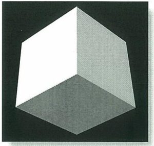
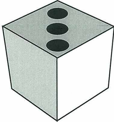
Two startling visual machinations embellished the already powerful one of corner reversing. What is in reality an inside corner structure appears to be a solid cube in its illusion mode, this illusion in itself is strong, and once established in the mind is difficult to undo.
But even more astonishing is the sluing effect which occurs when the viewer moves his position relative to the Slu cube. The damn thing follows him around the room, pivoting on its axis. Rather eerily disconcerting.
But, yet again, yet another surprise lay within. – later. At first the construction of the slue cube was done from basic perspective drafting technique. Models were built and evaluated, tweaked, eyeball improved angles and dimensions were carefully measured and recorded.
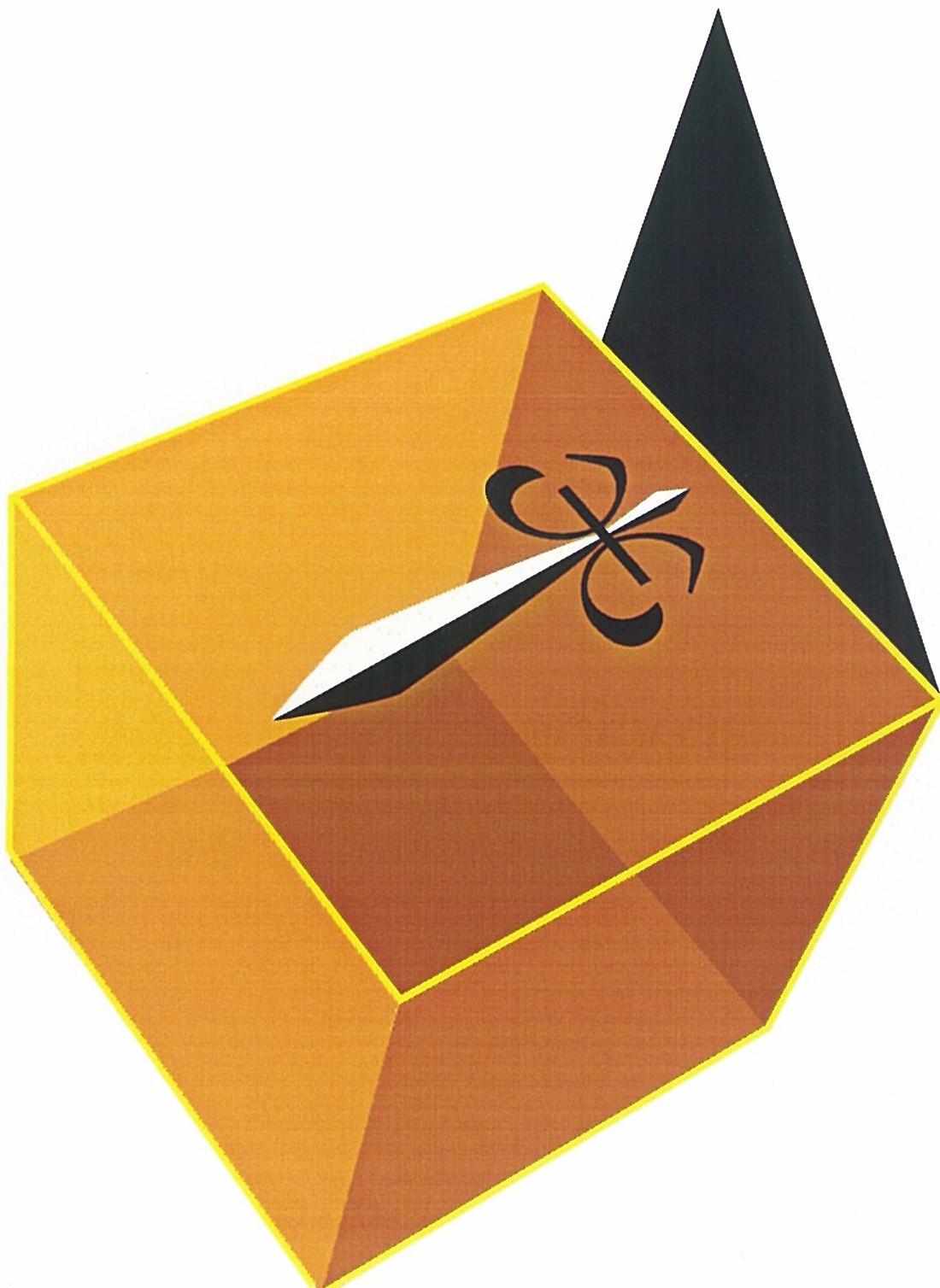
It was soon found that the illusion could be enhanced by applying geometric designs to the three visible surfaces of the structure if these designs were also drawn in the same perspective as the Slu cube panel surfaces were cut. The choice of words, lettering, typeface, also contributed to the effect.
But then it had become crushingly obvious that a high-end graphics computer, an apple Macintosh, which could digitally manipulate a precision perspectival drafting program was requisite. The apparatus was acquired; the program was too.
With the graphic and geometric capabilities of the digital machine, all sorts of patterns, designs, logos, etc. were cranked out of the laser printer, (black and white only) and affixed to small seven and one-half inch models for evaluation it is then that a most interesting new effect was discovered.
To see what if any effect color would have with this illusion various color photographs were cut to size and pasted into the illusion.
– egad! They went 3D
The figures in the Photographs Moved about inside their cube space seemingly independent of the cube’s own illusory movement. The human mind and its eyes were becoming curio user and curiouser. This illusion demanded serious cogitation.
At this writing the investigation casually continues. Larger structures have been built. Larger photographic color prints have been made and evaluated for their three-dimensional impact.
The ultimate impact upon the planet of this visual magic is dubious .it rests in the wry hands of Wrye.
What follows is a brief compilation of instructions, a sort of how-to manual for efficaciously creating Slu cubes exactly, and even precisely, in one own backyard. So to speak.
THE SLU CUBE – A SEVEN AND ONE HALF INCH TEMPLATE
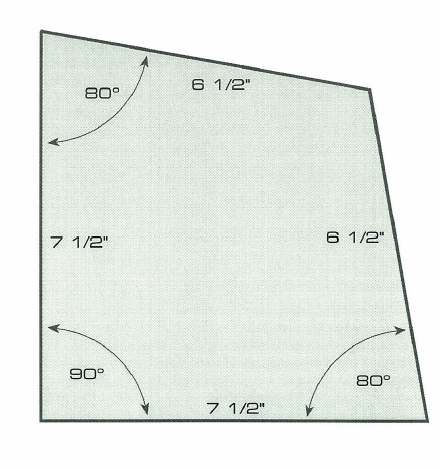
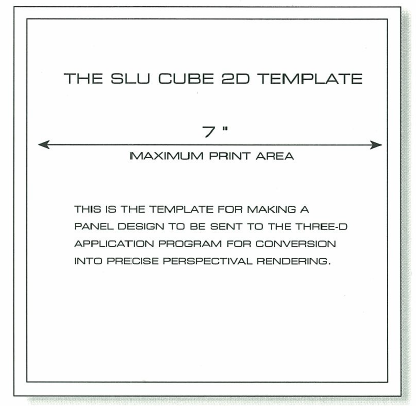
Pictured is the definitive Slu cube panel.it may be multiplied or divided in exact proportions to produce much larger or much smaller structures. This exact size was used as it was the largest that the letter-size laser-printer could accommodate in developing the illusion. Automatic tiled computer enlargements have been made for larger proposals.
Instructions for producing Slu cube images with an apple Macintosh Quadra 700 computer and the three dimensional drawing program follows on the next page.
THE SLU CUBE – PRINTING INSTRUCTIONS
| 1 | Open freehand v3.1 |
| 2 | Open Slu cube template* |
| 3 | Design panel on template |
| 4 | Set type for text if any |
| 5 | Convert type to paths in type menu |
| 6 | Save as original to desktop |
| 7 | Under file select export-converts to eps |
| 8 | Open satellite v 1.53 |
| 9 | Select extrusion from box |
| 10 | Choose no extrusion -ok |
| 11 | Open eps. File from desk top |
| 12 | Make 30 settings in appropriate boxes |
| 13 | Vertical -23 horiz +25 eye distance 17.b |
| 14 | Click show |
| 15 | Save 3d image in dialog box to desktop |
| 16 | Save as illustrator 1.1 option |
| 17 | Save situation to desktop |
| 18 | Quit satellite |
| 19 | Click freehand icon in menu bar finder box |
| 20 | Click open in file menu and select 3d illus eps file on desktop |
| 21 | Converts to untitled freehand file |
| 22 | Rename untitled “top 30 print” |
| 23 | Scale image t0 141% |
| 24 | With line tool extend hairline borders to paper edges to facilitate cutting |
| 25 | Label page at bottom ‘top” |
| 26 | |
| 27 | Cut to size on cut-lines |
* Reproduced on previous page
PRINTING RIGHT PANEL
| 1 | Open original drawing from desktop |
| 2 | Select all |
| 3 | Rotate entire image 180 degrees |
| 4 | Save to desktop as original right panel |
| 5 | Export as eps file to desktop |
| 6 | Open satellite |
| 7 | Repeat cycle as with top panel |
PRINTING LEFT PANEL
| 1 | Open original drawing from desktop |
| 2 | Select all |
| 3 | Rotate entire image -90 degrees |
| 4 | Save to desk top as original left panel |
| 5 | Export as eps file to desktop |
| 6 | Open satellite |
| 7 | Repeat cycle as with right panel |
Nota bene: with the continuing advances made in software and hardware technologies, these instructions will be of little use a few years down the road, but the reader will be able to glimpse the procedure, and if he wishes, fit it to the available, much more sophisticated technology of his moment in time.
HE SLU CUBE – DESIGN SLU CUBE PANELS
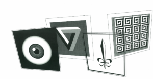
Displayed here are a few of the black and white panel designs created on the computer for the prototype Slu cubes.
THE SLU CUBE – TYPOGRAPHIC SLU CUBE PANELS
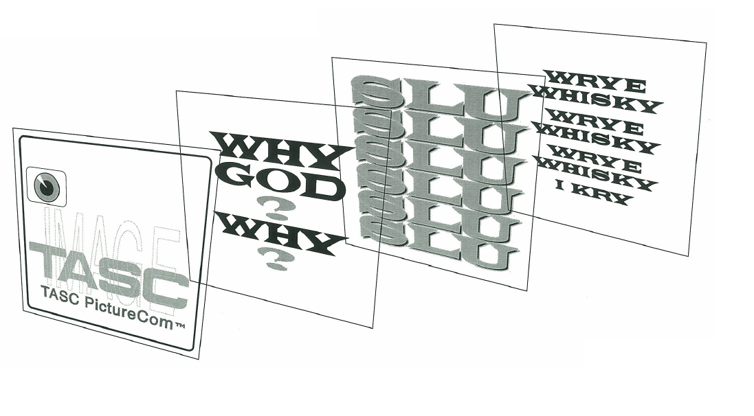
THE PANELS DISPLAYED HERE ARE THE LEFT PANELS OF SOME OF THE TYPOGRAPHIC SLU CUBES. THE FOLLOWING PAGE SHOWS HOW THREE PANELS-RIGHT, LEFT, TOP-FIT TOGETHER TO CREATE THE SLU CUBES STRUCTURE.
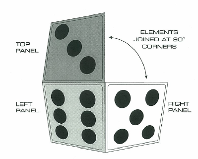
THE SLU CUBE -ASSEMBLY OF THE STRUCTURE
Prototype Slu cube panels were cut from .050″ styrene sign sheet and taped together on the reverse side. Later the panels were cut .05 0 ” oversize on one edge to permit overlapping the interior edges and chemical welding with methyl ethyl ketone, while still maintaining exact interior dimensions.
The designs, printed in computer generated perspective, were then cemented to the three styrene panels – left, top, and right.
It must be understood that the three panels -top, left, and right, are joined together to form an inside corner with the printed design elements fixed to the inside walls.
ILLUSORY TOP PANEL
LEFT PANEL RIGHT PANEL
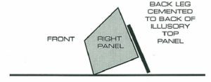
A styrene panel 4” x 8″ was cemented to the back of the top panel extending below the 90 ° corner 4• to form a leg so that the cube rests on a point. This is, of course, a description of putting together the small styrene plastic prototype Slu cube for preliminary pre-emptory evaluation of its art and illusive effectiveness.
Applied designs may be silkscreen, flexographic, offset, or computer laser and plotter printed – or other – from photographs or original designs – or other.
Larger or smaller, more elaborate Slu cubes may be built of many sorts of materials depending on the demands of their use. – wood, carved wood panels, stamped sheet metal, cast bronze or aluminum in sculpted relief, chiseled stone, cast concrete, Plexiglas, fiber-glass, etc. Are among the candidates.
Glass or mirrors, glossy prints, and other reflective surfaces ought to be avoided as interior reflections destroy the illusion.
– An interesting discovery – reliefs must be inverted, as incised cuts seem to stand proud in the illusion perception mode.